3 · v0.1 · draft · 2026-08-08
| Doctype | Test Report |
|---|---|
| Product line | openvvvf |
| Applies to | openvvvf-control-module, chassis-size-2 |
| Version | 0.1 |
| Date | 2026-08-08 |
| Status | draft |
| Description | Sanity check of the resistance calibration routine using a known power-resistor load. |
| Test id | 3 |
| Nav order | 345 |
| Normative refs | OV-TEST-HW-MOTOR-CAL-INDEX, OV-TEST-HW-INDEX |
Power Resistor Sanity Check
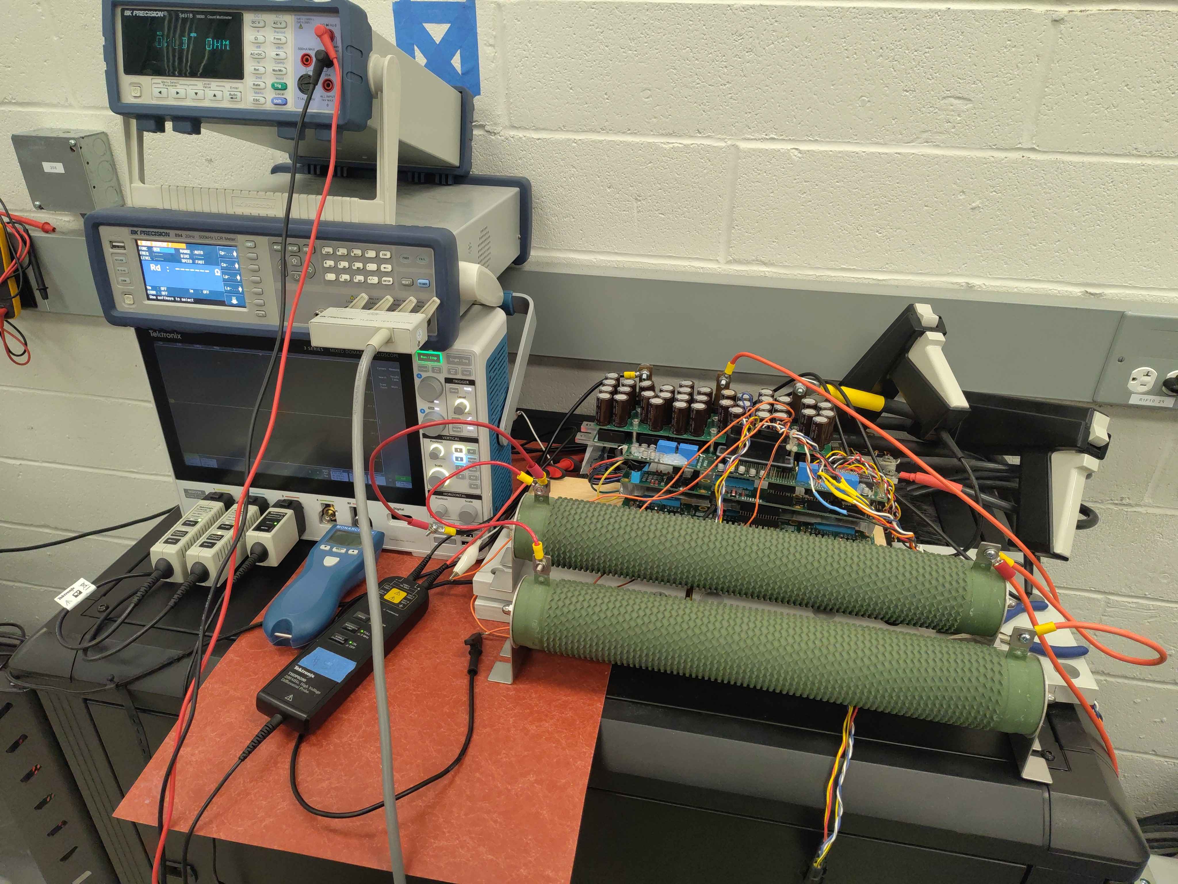
This report checks that the cal Motor.Resistance routine returns a sensible value for a purely resistive, high-impedance load. A known power resistor was connected across two inverter phases; the routine's estimate is compared against a direct LCR measurement.
Test setup
- Load: 23 Ω power resistor tied across phases U and V.
- DC bus: ~121 V.
- Chassis: C2 test fixture.
- Command:
cal Motor.Resistance 8.0 --force.
Instrument reference
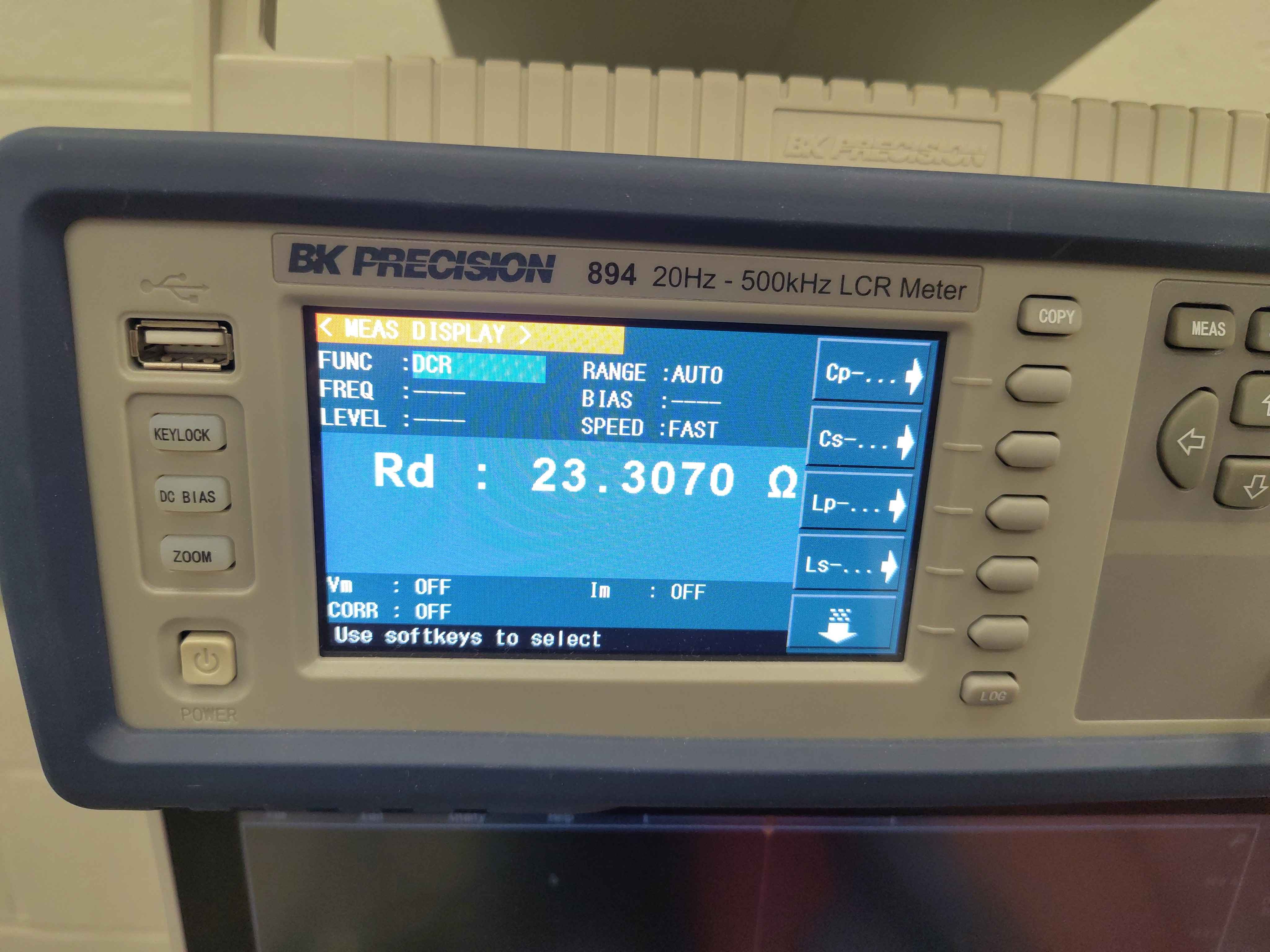
- Instrument: BK Precision 894 20 Hz - 500 kHz LCR Meter
- Function: DCR
- Range: AUTO
- Speed: FAST
| Parameter | Value |
|---|---|
| Rd | 23.3070 Ω |
Inverter-calibrated resistance
| Parameter | Value |
|---|---|
| Calibrated UV line-to-line | 20.94 Ω |
| Calibrated UV per-phase | 10.47 Ω |
| Max current reached (UV) | 0.345 A |
| Fit offset (V_off) | 23.6 V |
| UW measurement | Failed (non-positive resistance) |
Open telemetry log: View this calibration in the Telemetry Viewer
- Command log: PowerResistor-Command-Log.txt
- Raw telemetry: PowerResistor-Telemetry.jsonl
Analysis
The reading is about 9 % low (20.94 Ω vs 23.31 Ω reference). That is expected for this test point because the current was pushed down by the high resistance load.
At ~0.3 A the IGBTs are operating in the knee region, where
Vce ≈ Vf(knee) + Ic · Rce(on)
The knee voltage across the two conducting IGBTs is large compared with the ~6-7 V across the resistor, so the linear fit absorbs most of the knee as an offset. Because the knee is slightly curved, the slope is biased low. The 23.6 V fit offset is consistent with this explanation.
The UW phase failed because the resistor was not connected across U-W; the measured current had the wrong sign and the fit produced a negative resistance. This is normal for a single-pair measurement.
This result is not motor-grade accuracy, but it confirms the calibration is in the right decade and is not producing the milliohm-scale nonsense that appears when the routine is run without a real load.
Notes
- For a real motor with line-to-line resistance of a few ohms or less, the routine can push tens of amps, the IGBT knee becomes a small fixed offset, and the fit accuracy improves significantly.
- A repeat test with a lower-value resistor or higher bus voltage would move the operating point above the IGBT knee and give a closer match to the reference.