8 · v0.1 · draft · 2026-08-09
| Doctype | Test Report |
|---|---|
| Product line | openvvvf |
| Applies to | openvvvf-control-module, chassis-size-2 |
| Version | 0.1 |
| Date | 2026-08-09 |
| Status | draft |
| Description | Bring-up run of the C2 power stage with 200 V capacitors, driving the TECO MAX-IE3 induction motor up to 180 VDC bus. |
| Test id | 8 |
| Nav order | 355 |
| Normative refs | OV-TEST-HW-INDUCTION-CAL-INDEX, OV-TEST-HW-INDUCTION-NOLOAD-1H, OV-TEST-HW-INDEX |
Induction Motor 180 V Power Stage Bring-up
This report records the first time the C2 power stage was operated with 200 V DC-link capacitors at elevated bus voltage. The TECO MAX-IE3 induction motor was used as a load while the DC bus was stepped from ~140 V up to ~180 V to validate capacitor hold-off, gate-drive operation, and current regulation at the higher rail.
Test setup
- Motor: TECO Westinghouse MAX-IE3 3-phase induction motor, 10 HP / 7.5 kW, 208 V, 60 Hz
- Inverter: OpenVVVF C2 chassis with 200 V DC-link capacitors
- Control: V/Hz open-loop excitation, no mechanical load
- Instrumentation: Tektronix 5 Series MSO oscilloscope, controller telemetry
Test conditions
| Parameter | Value |
|---|---|
| DC bus voltage | stepped 140 V -> 150 V -> 170 V -> 180 V |
| Commanded frequency | ~60 Hz |
| Mechanical load | None (free spinning shaft) |
| Duration | ~10 min (604 s) |
| Ambient temperature | ~23 °C |
Electrical observations
The telemetry plot below shows the entire bring-up sequence. The DC bus was increased in discrete steps while the motor remained under V/Hz excitation. Phase current magnitude grew with bus voltage as expected for a no-load magnetizing characteristic, reaching brief peaks above 35 A during transients.
Key events from the log:
| Time (s) | Bus voltage | Observation |
|---|---|---|
| 0 - 160 | ~142 V | Stable no-load excitation, small currents |
| ~160 - 180 | dip to ~30 V then back to ~142 V | Bench supply current limit was too low; motor slip kept current demand high, collapsing the bus until the current limit was raised |
| 180 - 320 | ~142 V | Continued stable operation |
| 320 - 420 | ~152 V | First voltage step; currents remain moderate |
| 420 - 520 | ~172 V | Second voltage step; current ripple increases |
| ~520 | data pauses | control stop halted the ISR and telemetry; control start resumed sampling |
| 520 - 560 | ~172 V | Operation resumes after control restart |
| 560 - 604 | ~181 V | Final step to ~180 V; peak phase current ~38 A |
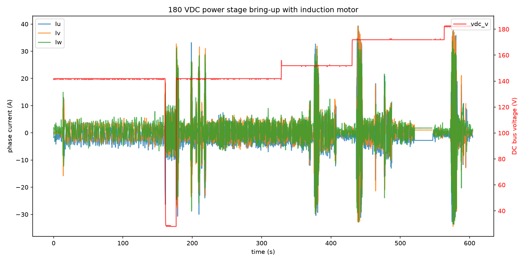
Open telemetry log: View the 180 V bring-up in the Telemetry Viewer
Results
- The 200 V capacitor bank held the ~180 V rail without issue.
- Gate-drive and current sensing operated correctly across all voltage steps.
- The controller recovered cleanly after the ~160 s bus collapse once the bench supply current limit was raised.
- Maximum observed DC bus voltage: 182.5 V.
- Maximum observed phase current (transient): ~38 A.
- Telemetry was paused around 520 s by
control stopand resumed withcontrol start; no data was lost in the JSONL export.
Conclusion
The C2 power stage with 200 V DC-link capacitors successfully ran at 180 VDC while driving the induction motor. This confirms the hardware is usable for nominal 200 V-class DC buses and provides confidence for future higher-voltage loaded tests.
Artifacts
Notes
- The full-rate telemetry log is ~157 MB; the linked file is decimated to 0.2 samples per second for the repository.
- This was an unloaded motor test; loaded current levels at 180 V will be higher and require additional validation.