2 · v0.1 · draft · 2026-08-08
| Doctype | Test Report |
|---|---|
| Product line | openvvvf |
| Applies to | openvvvf-control-module, chassis-size-2 |
| Version | 0.1 |
| Date | 2026-08-08 |
| Status | draft |
| Description | Validation of the inverter motor-inductance calibration routine against a bench LCR reference. |
| Test id | 2 |
| Nav order | 344 |
| Normative refs | OV-TEST-HW-MOTOR-CAL-INDEX, OV-TEST-HW-INDEX |
PMSM Inductance Calibration Validation
This report validates the inverter's motor-inductance calibration routine by comparing its estimate against a direct bench LCR measurement of the test motor. The test was run on the C2 chassis test fixture, but the routine itself is shared across all OpenVVVF chassis; motor-specific validation is only needed when a different motor or harness is used.
Resistance reference measurements are kept in the PMSM Resistance Calibration Validation report.
A separate induction-machine test report is in Induction Motor Testbed.
Test setup
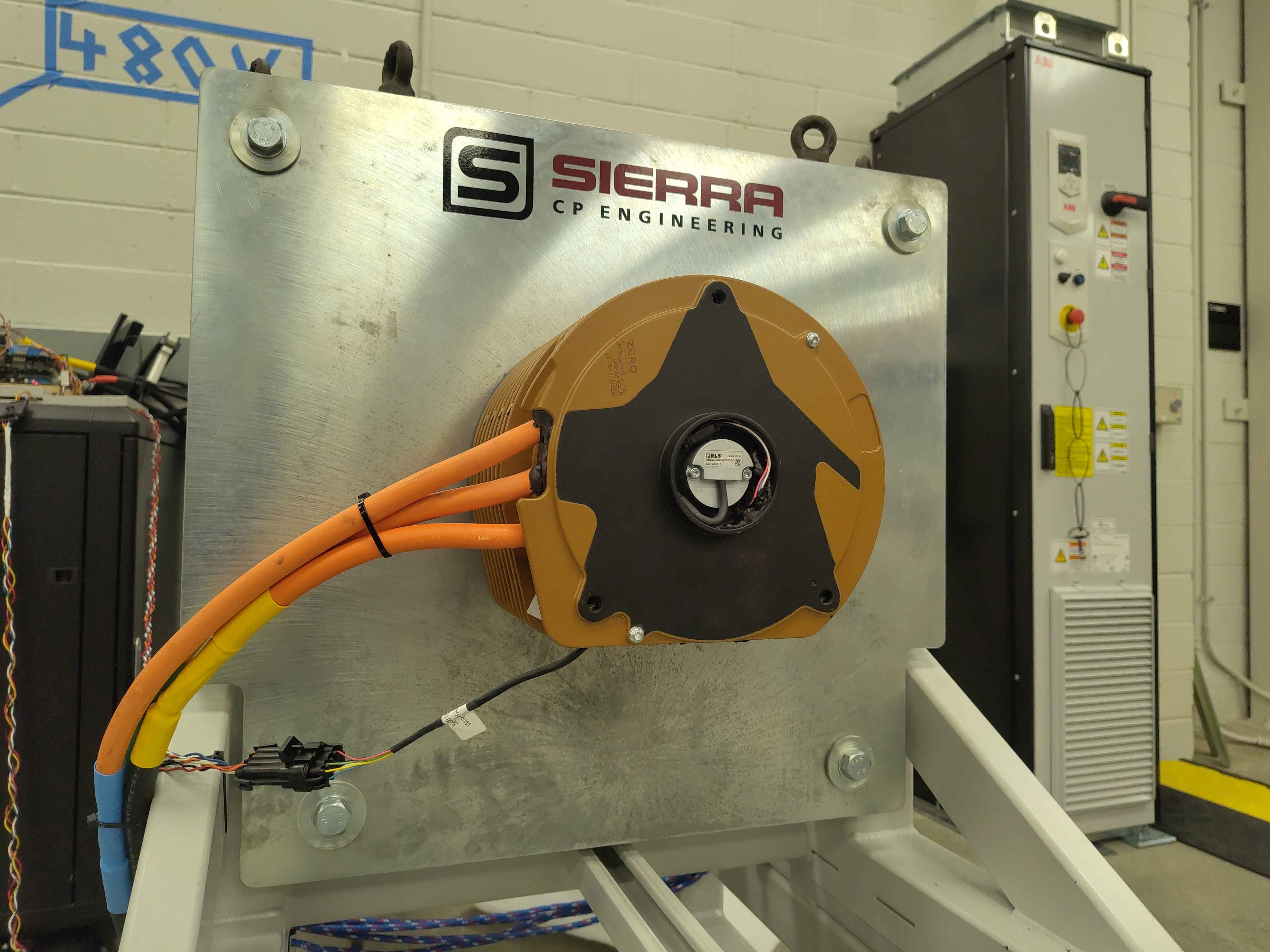
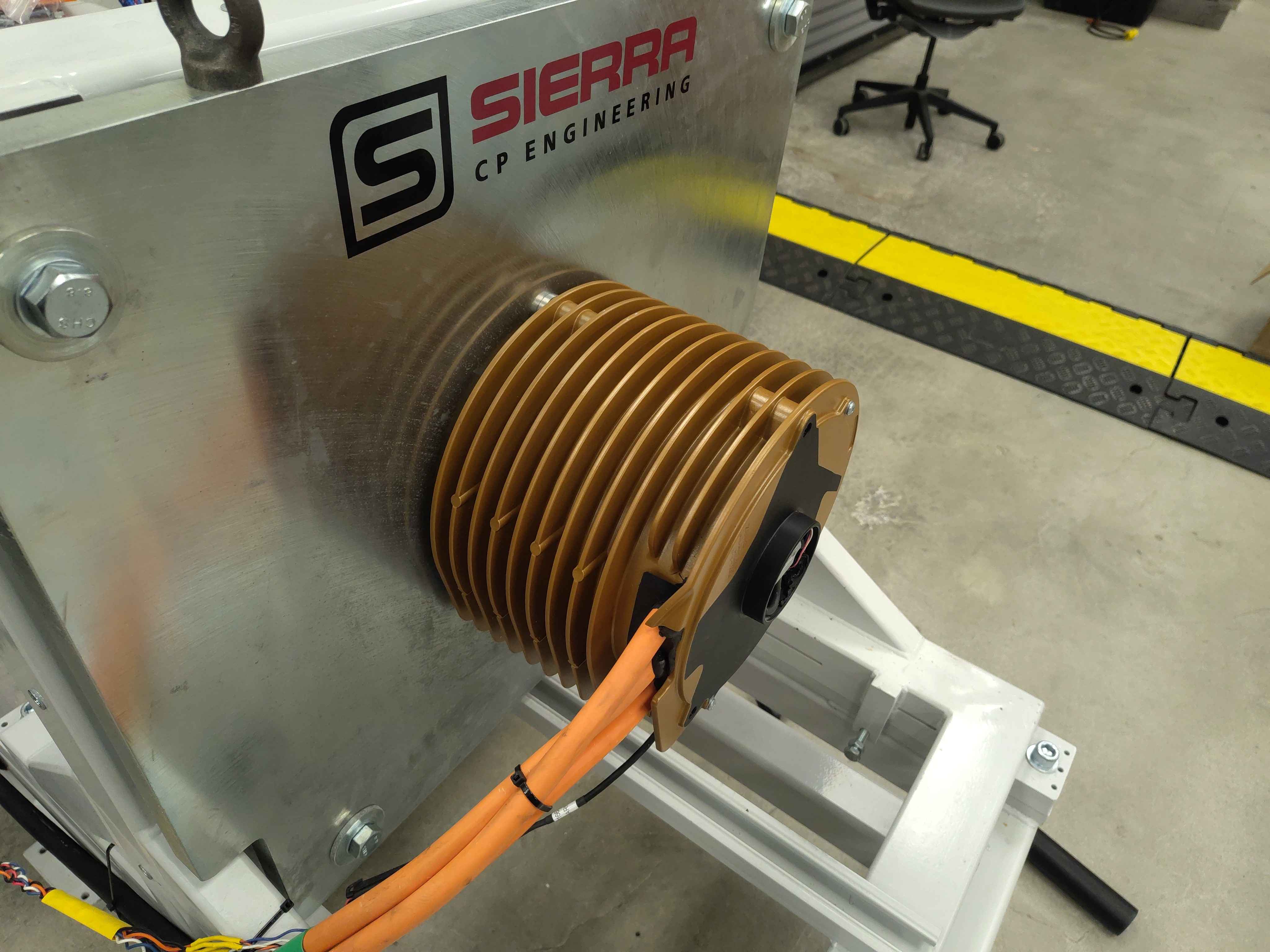
The motor is mounted on the Sierra CP Engineering test fixture with phase leads accessible for direct LCR measurement.
Instrument
- Instrument: BK Precision 894 20 Hz - 500 kHz LCR Meter
- Test frequency: 1.000 kHz
- Test level: 2.000 V
- Bias: 0.00 mV
- Range: AUTO
Measurements
Phase inductance and series resistance (Ls-Rs)
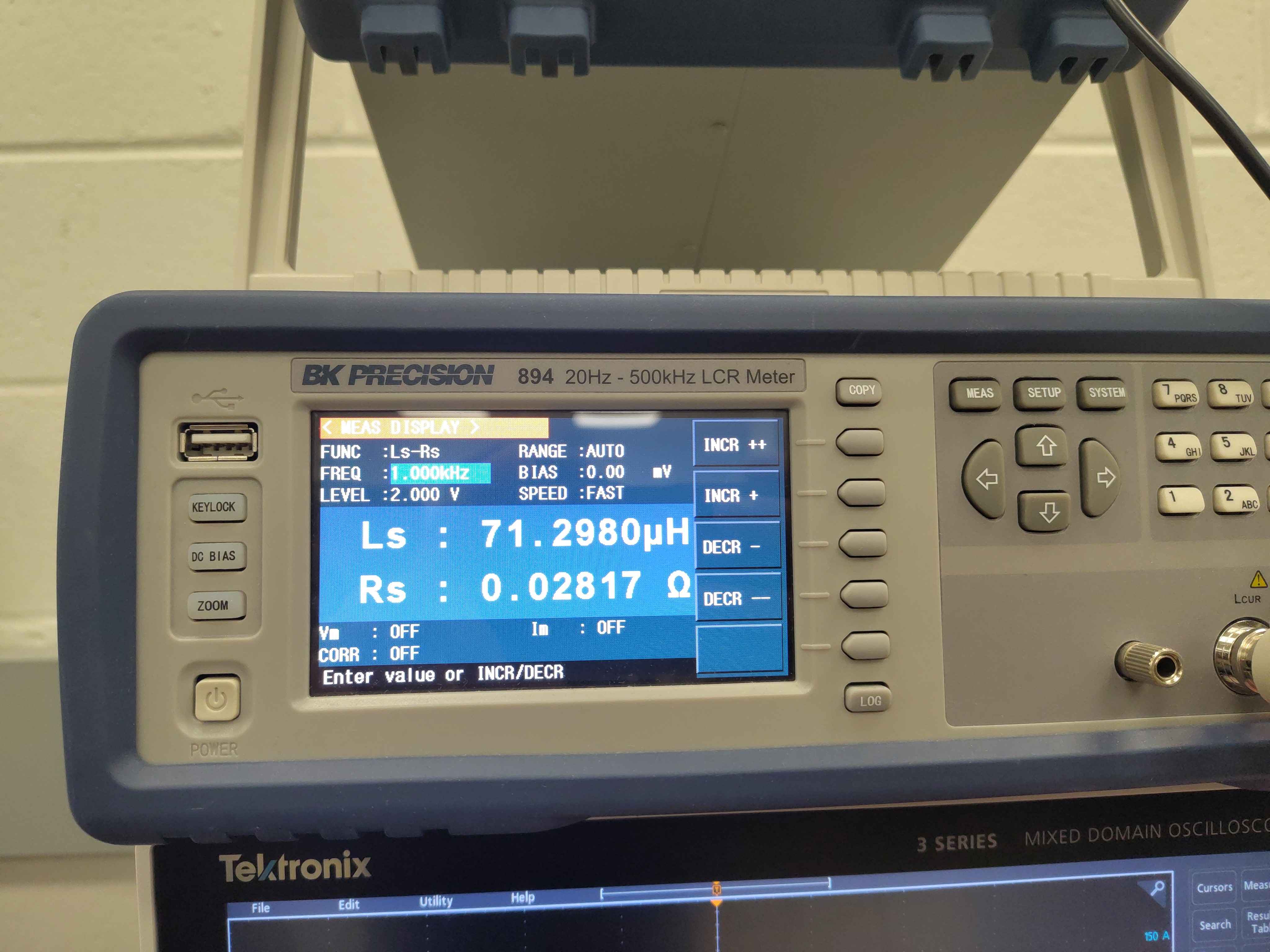
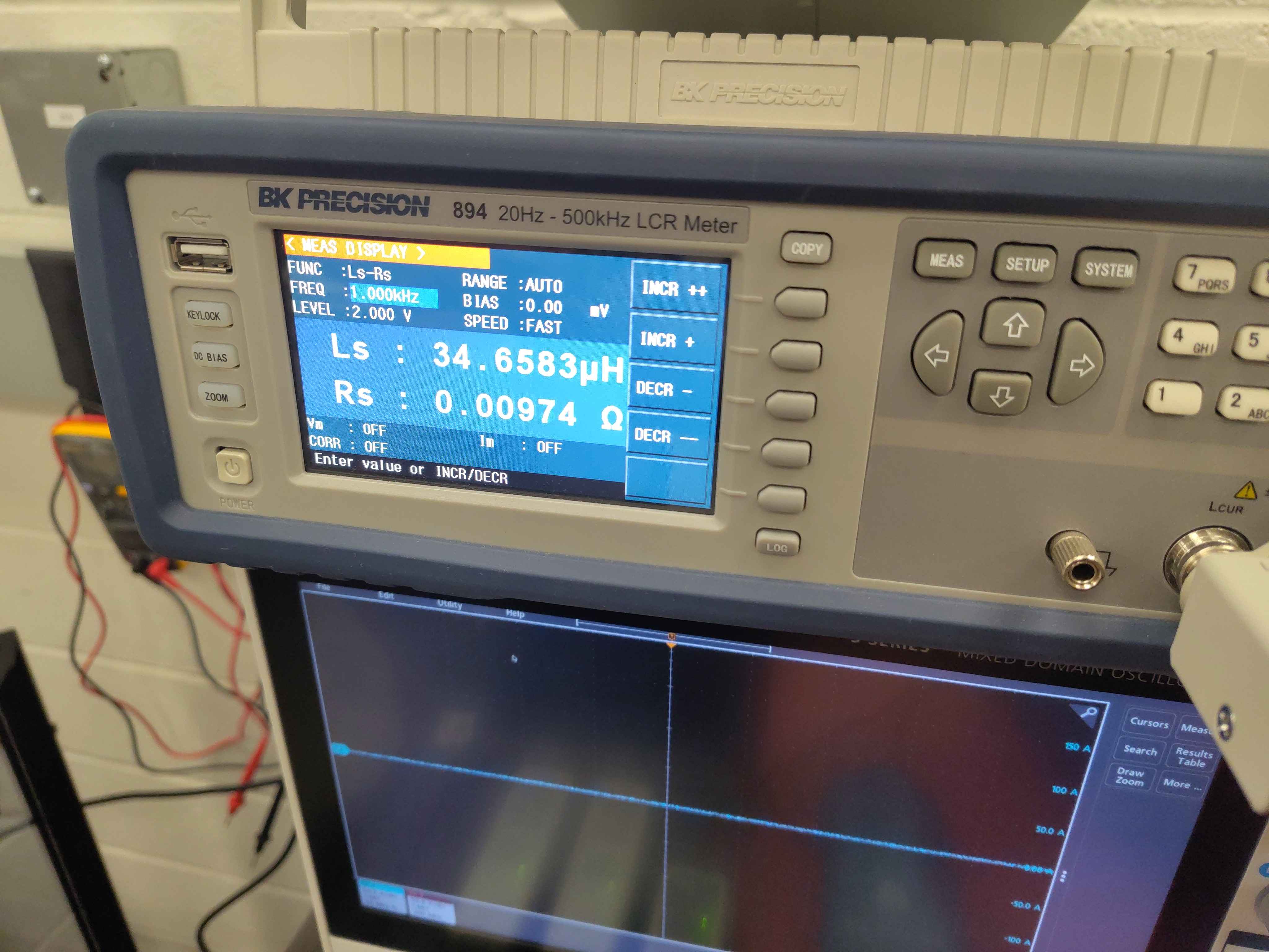
Two Ls-Rs readings were captured at 1.000 kHz.
| Reading | Ls | Rs | Instrument settings |
|---|---|---|---|
| 1 | 71.2980 µH | 0.02817 Ω | FUNC: Ls-Rs, FREQ: 1.000 kHz, LEVEL: 2.000 V, RANGE: AUTO, SPEED: FAST |
| 2 | 34.6583 µH | 0.00974 Ω | FUNC: Ls-Rs, FREQ: 1.000 kHz, LEVEL: 2.000 V, RANGE: AUTO, SPEED: FAST |
Inverter-calibrated inductance
The inverter's inductance calibration routine will be run and its output compared against the LCR reference readings above. Add the command log, telemetry, and comparison table here.
Notes
- The Ls-Rs readings are series inductance and resistance at 1 kHz.
- Which phase pair or winding configuration each Ls-Rs reading corresponds to should be recorded when the calibration routine results are compared against these reference values.