4 · v0.1 · draft · 2026-08-08
| Doctype | Test Report |
|---|---|
| Product line | openvvvf |
| Applies to | openvvvf-control-module, chassis-size-2 |
| Version | 0.1 |
| Date | 2026-08-08 |
| Status | draft |
| Description | Base documentation for the TECO MAX-IE3 induction motor testbed used for calibration validation. |
| Test id | 4 |
| Nav order | 351 |
| Placeholder | True |
| Normative refs | OV-TEST-HW-INDUCTION-CAL-INDEX, OV-TEST-HW-INDEX |
Induction Motor Testbed
Placeholder - add photos of the fixture, phase-lead access, and any additional instrumentation once the testbed is fully wired.
This document describes the induction-motor testbed used to validate the OpenVVVF motor self-commissioning routines. The same physical setup is used for both the resistance and inductance calibration reports.
Motor under test
| Parameter | Value |
|---|---|
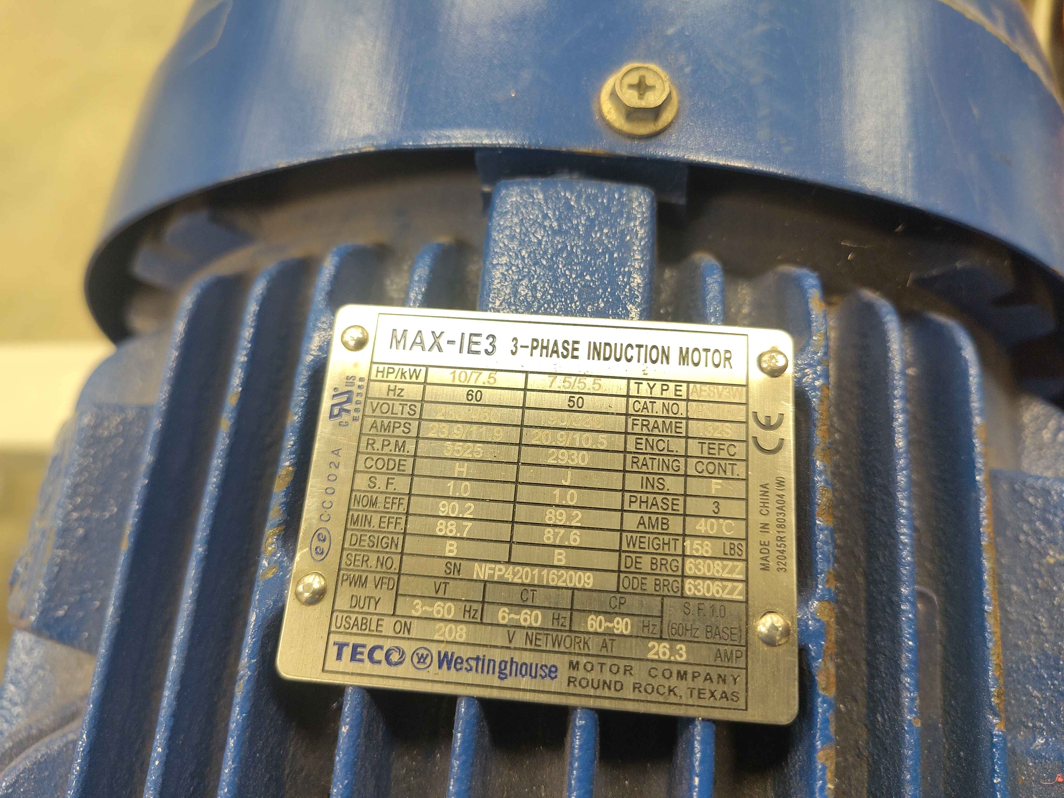
| Manufacturer | TECO Westinghouse |
| Model | MAX-IE3 3-phase induction motor |
| Type | Squirrel-cage induction machine |
| Power | 10 HP / 7.5 kW |
| Frequency | 60 Hz base |
| Voltage | 208 V network |
| Current | 26.3 A |
| Enclosure | TEFC |
Test fixture
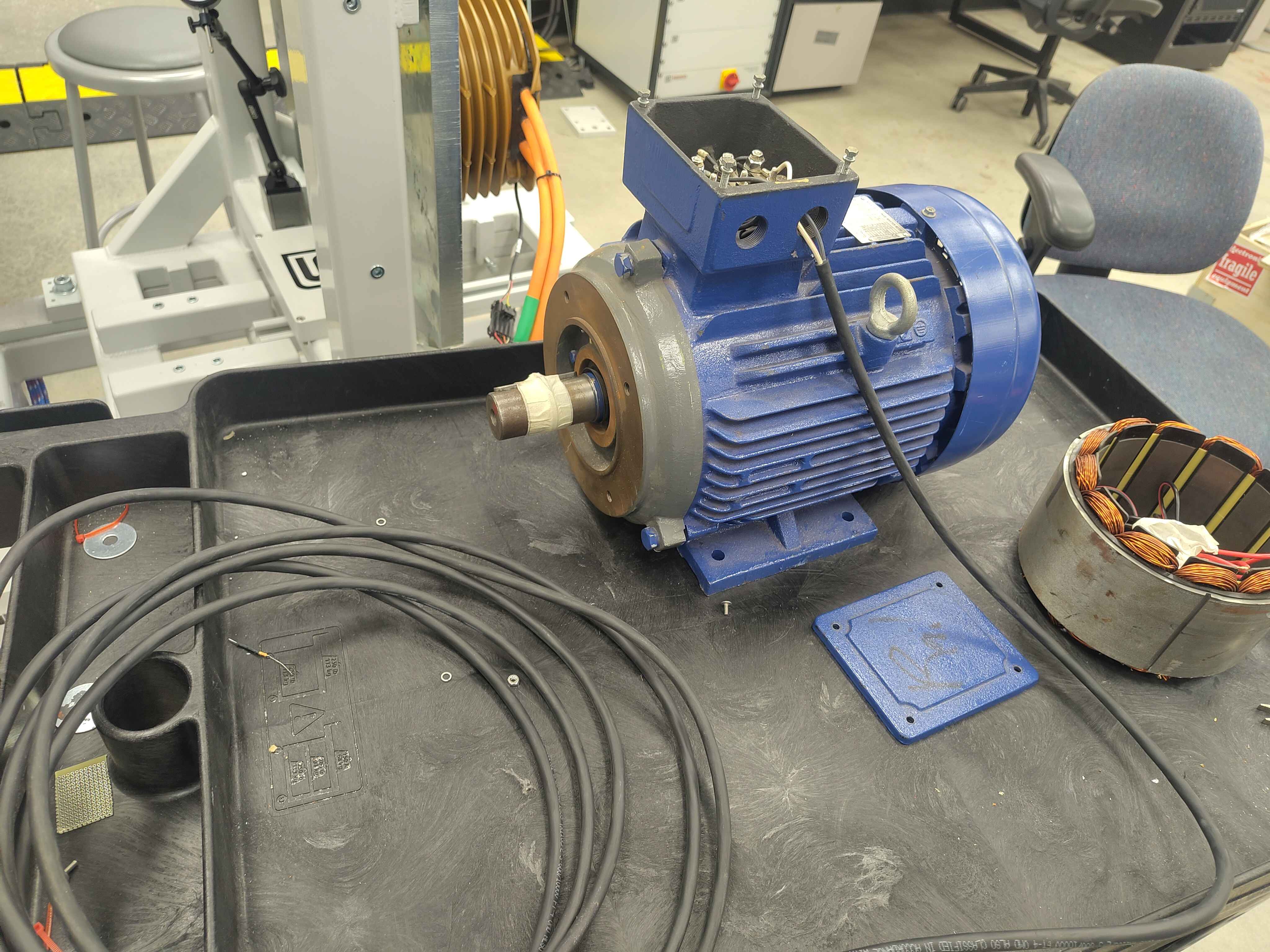
The motor is mounted on a bench fixture with the conduit box open so the three phase leads are accessible for direct bench measurement and for connection to the inverter output. A shaft coupling/cover is used for basic mechanical safety during no-load electrical tests.
Instrumentation
- LCR meter: BK Precision 894 (20 Hz - 500 kHz)
- Used for DCR (DC resistance) reference measurements.
- Used for Ls-Rs (series inductance / resistance) reference measurements at 1 kHz.
- Inverter: OpenVVVF C2 chassis test fixture.
- DC supply: Variable DC bus for the inverter.
- Current measurement: Inverter phase-current sensors and independent current probe for cross-check.
Wiring and access
- Phase leads U, V, W are accessed at the motor conduit box.
- For LCR measurements the inverter is disconnected and the LCR meter is connected directly across the phase pair being measured.
- For inverter calibration runs the motor is connected to the C2 inverter output through appropriately rated cabling.
Safety notes
- The motor is a rotating machine; keep guards in place whenever power is applied.
- Lock out the inverter DC bus and discharge the DC-link capacitors before connecting or disconnecting leads.
- Verify phase rotation and current limits before running the calibration routine.