7 · v0.1 · draft · 2026-08-09
| Doctype | Test Report |
|---|---|
| Product line | openvvvf |
| Applies to | openvvvf-control-module, chassis-size-2 |
| Version | 0.1 |
| Date | 2026-08-09 |
| Status | draft |
| Description | One-hour no-load run of the TECO MAX-IE3 induction motor at 120 VDC to establish a gate-driver and system thermal baseline. |
| Test id | 7 |
| Nav order | 354 |
| Normative refs | OV-TEST-HW-INDUCTION-CAL-INDEX, OV-TEST-HW-INDEX |
Induction Motor 1-Hour No-Load Test
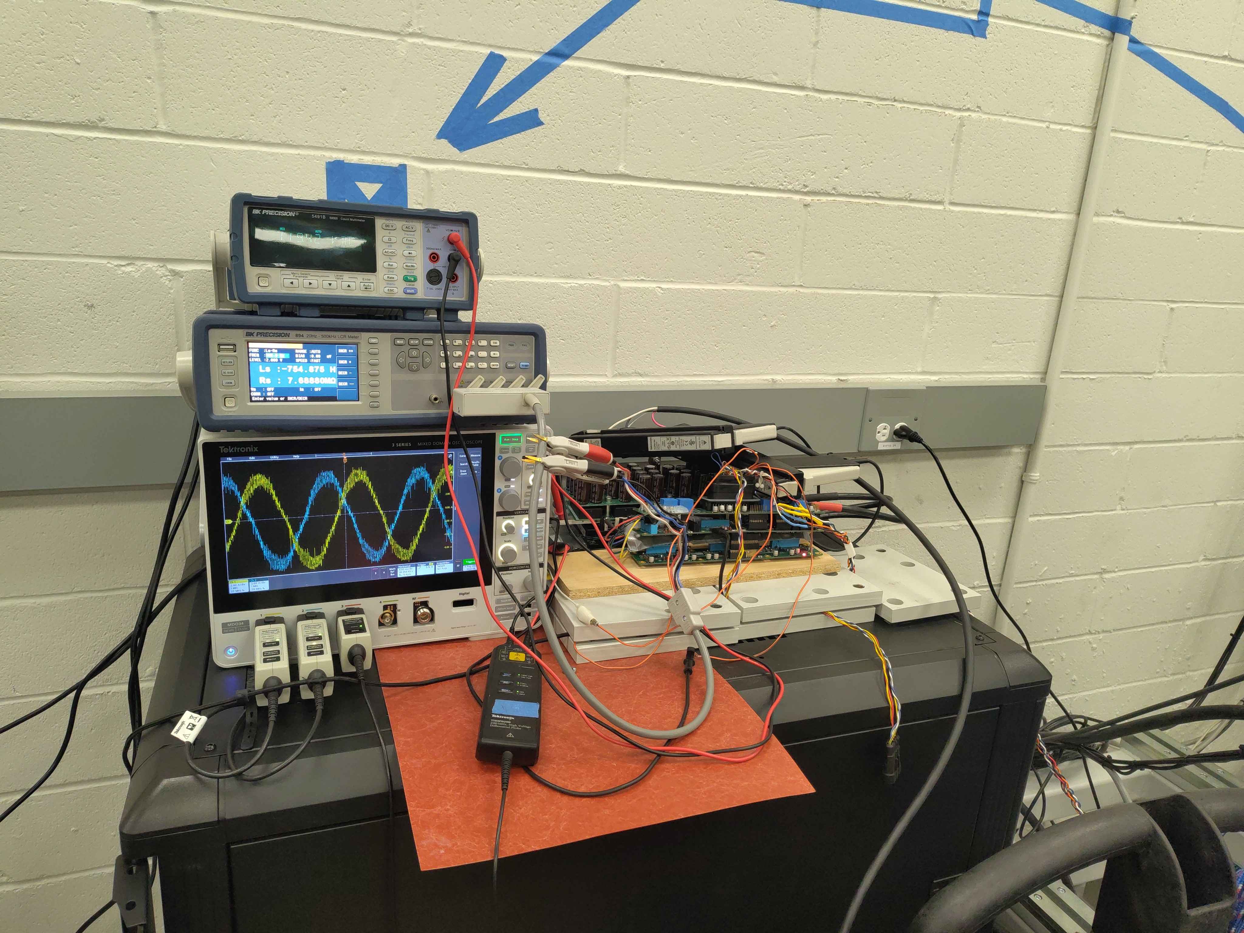
This report records a one-hour no-load run of the TECO MAX-IE3 7.5 kW induction motor powered by the C2 chassis inverter at 120 VDC. The objective is to validate gate-driver switching, confirm stable V/Hz operation, and capture a thermal baseline for the power stage and motor under light load.
Test setup
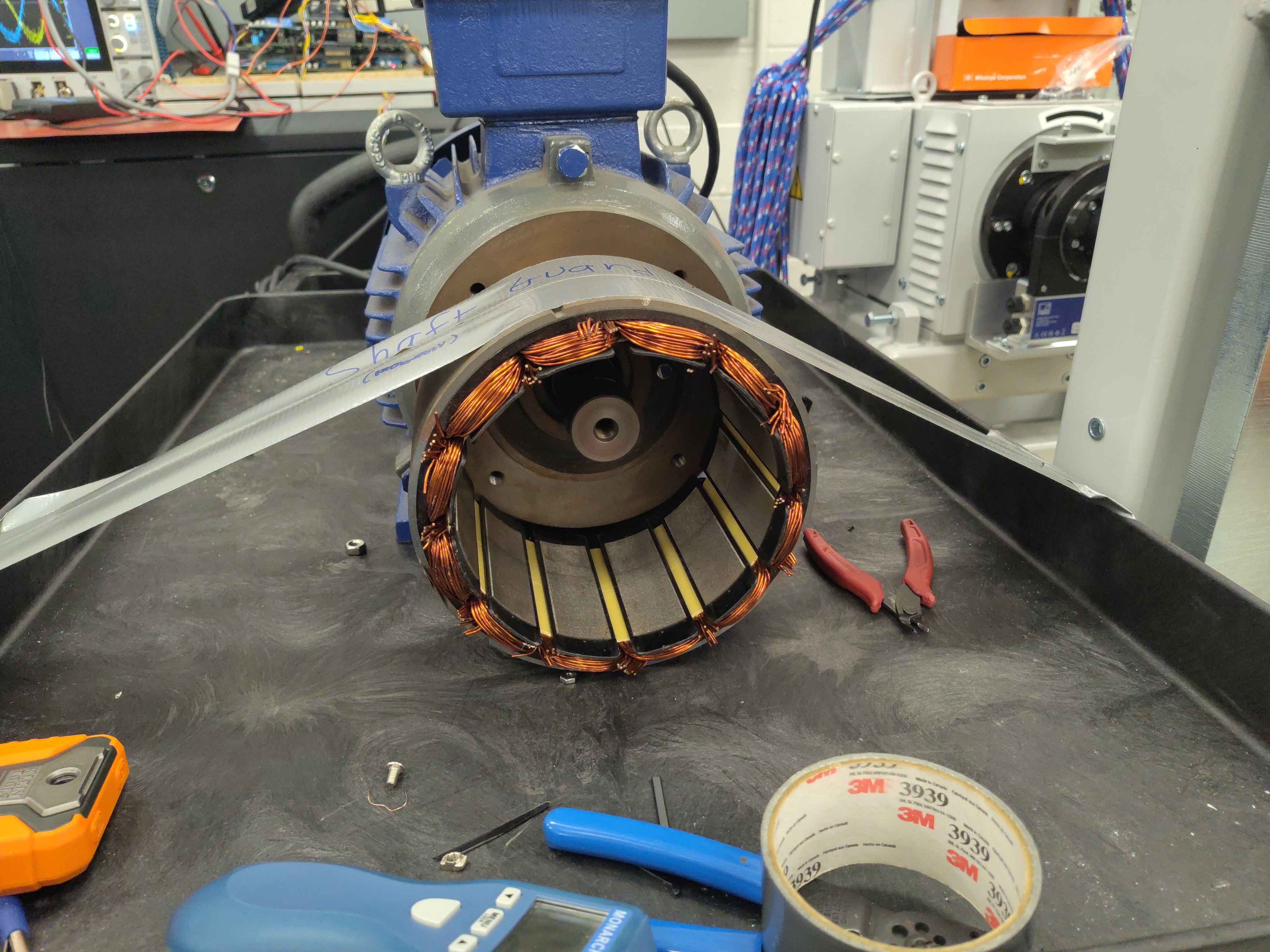
- Motor: TECO Westinghouse MAX-IE3 3-phase induction motor, 10 HP / 7.5 kW, 208 V, 60 Hz
- Inverter: OpenVVVF C2 chassis, 120 VDC bus
- Control: V/Hz open-loop excitation, ~60 Hz, no mechanical load
- Instrumentation: Tektronix 5 Series MSO oscilloscope, BK Precision 894 LCR meter, Klein Tools TI250 thermal imager
Test conditions
| Parameter | Value |
|---|---|
| DC bus voltage | 120 VDC |
| Commanded frequency | ~60 Hz |
| Mechanical load | None (free spinning shaft) |
| Duration | 1 hour |
| Ambient temperature | ~23 °C |
Thermal results
Thermal images were taken at several points during the run.
Motor temperature at start
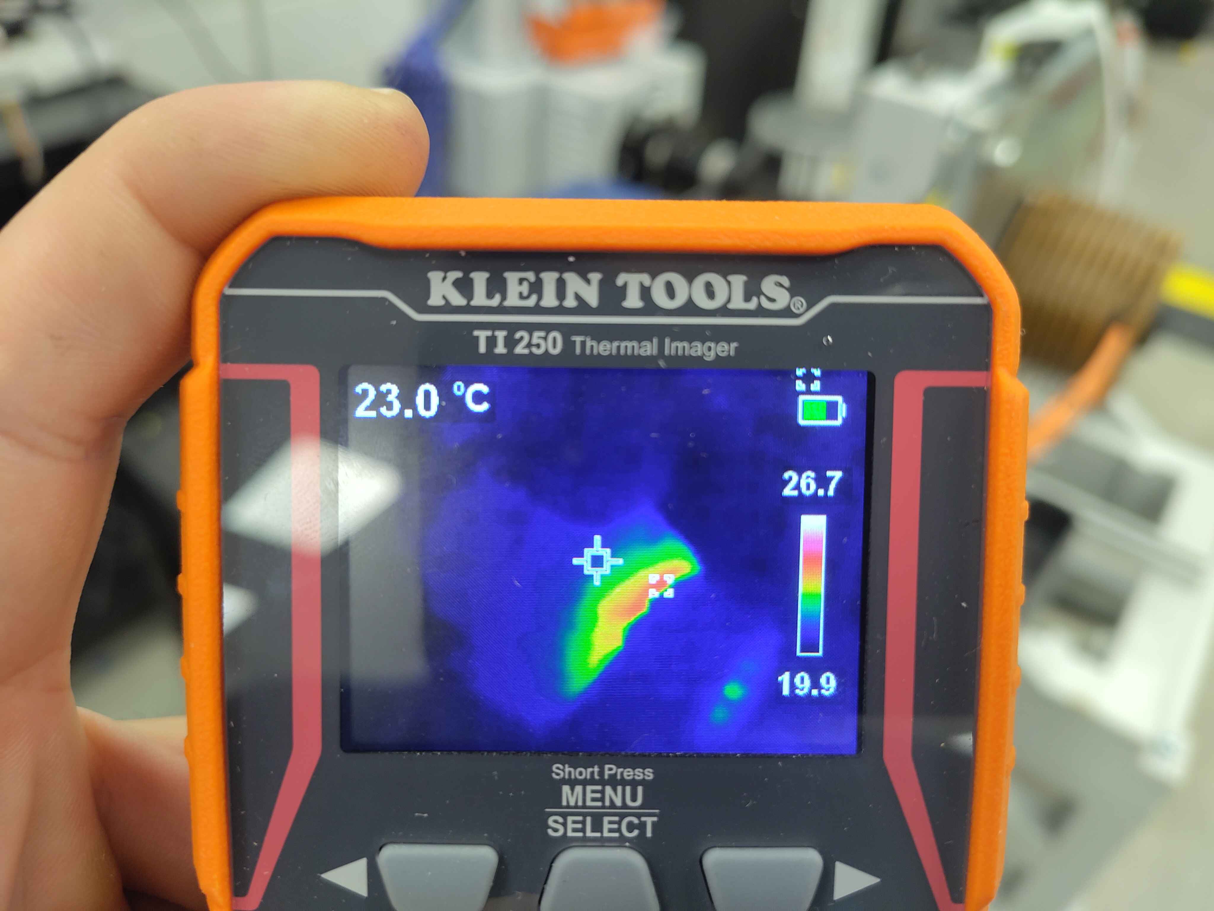
- Elapsed: ~7 min
- Approximate hotspot: ~27 °C
- Notes: Frame barely above ambient.
Power stage temperature near end
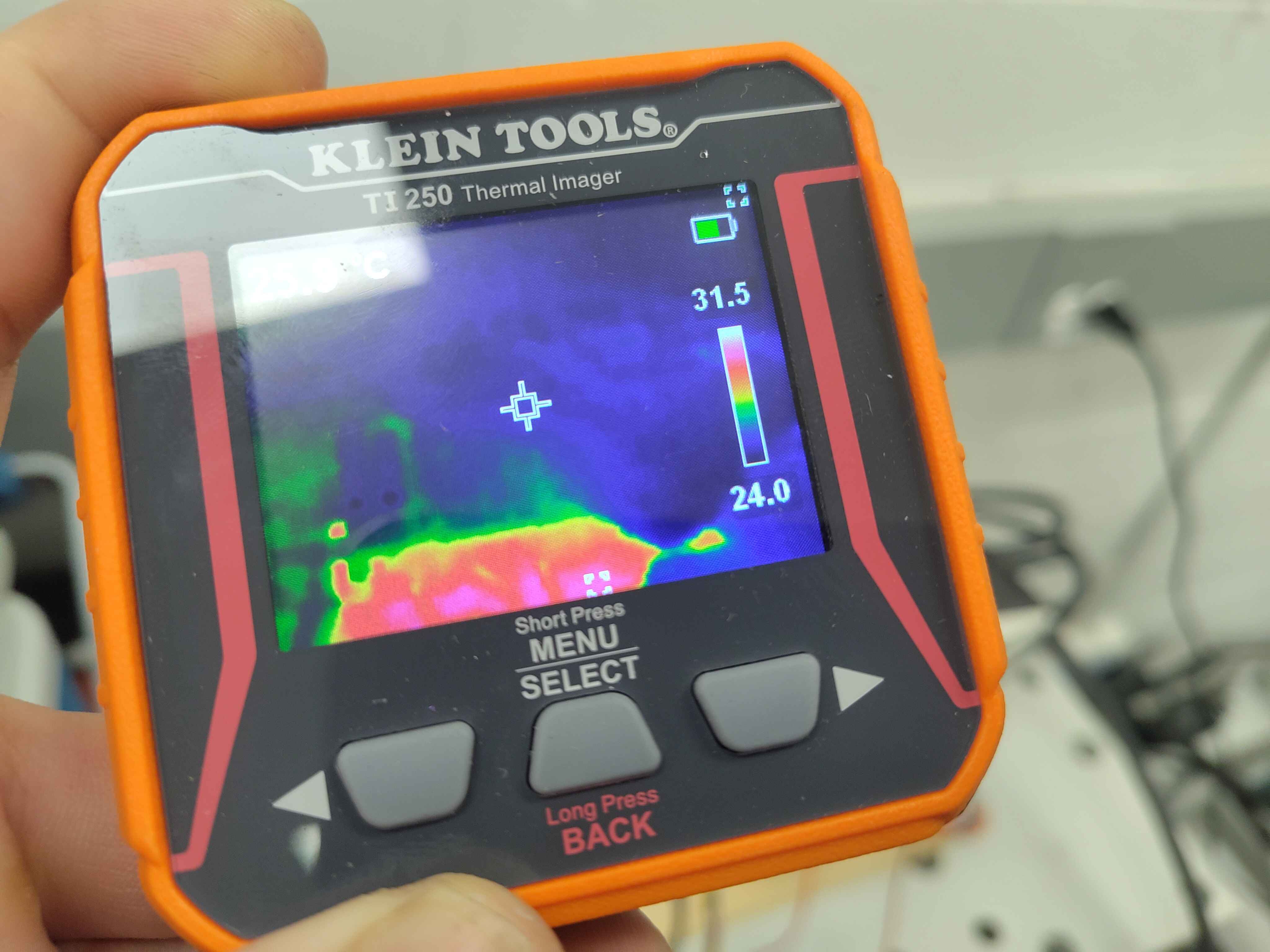
- Elapsed: ~21 min
- Approximate hotspot: ~29 °C
- Notes: Slow, steady rise on the power stage.
Hottest component: gate driver
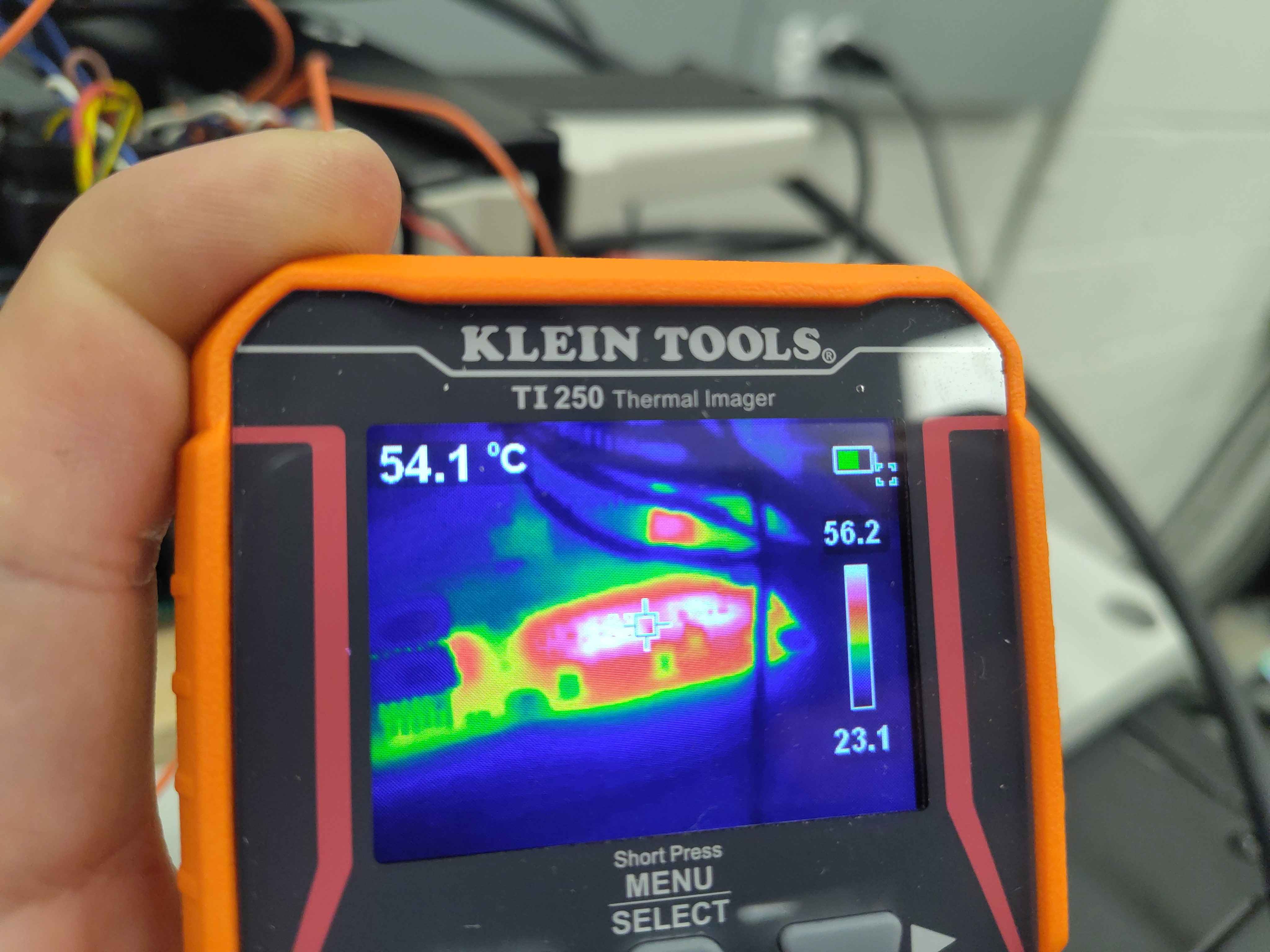
- Elapsed: ~51 min
- Approximate hotspot: ~56 °C
- Notes: Motor shell clearly warm; this shot captures the warmest region on the gate-driver board.
Motor temperature near end
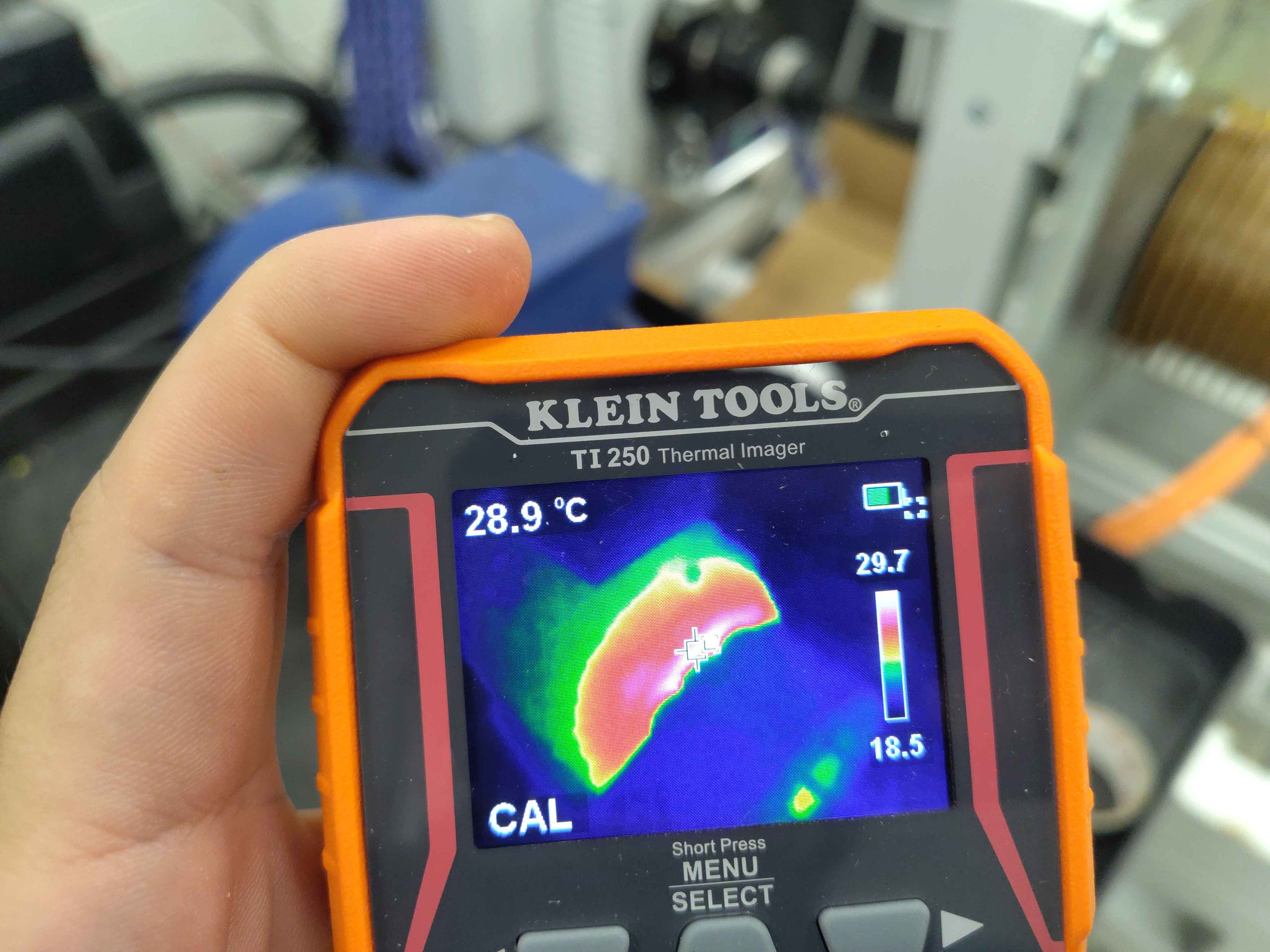
- Elapsed: ~57 min
- Approximate hotspot: ~30 °C
- Notes: Different spot on the frame / terminal box area.
Electrical observations
The inverter maintained stable V/Hz excitation for the full hour. Telemetry shows the DC bus held at ~121 V and the phase currents remained small, consistent with a no-load magnetizing current. The plot below is a decimated view of the entire run; the full interactive log is linked underneath.
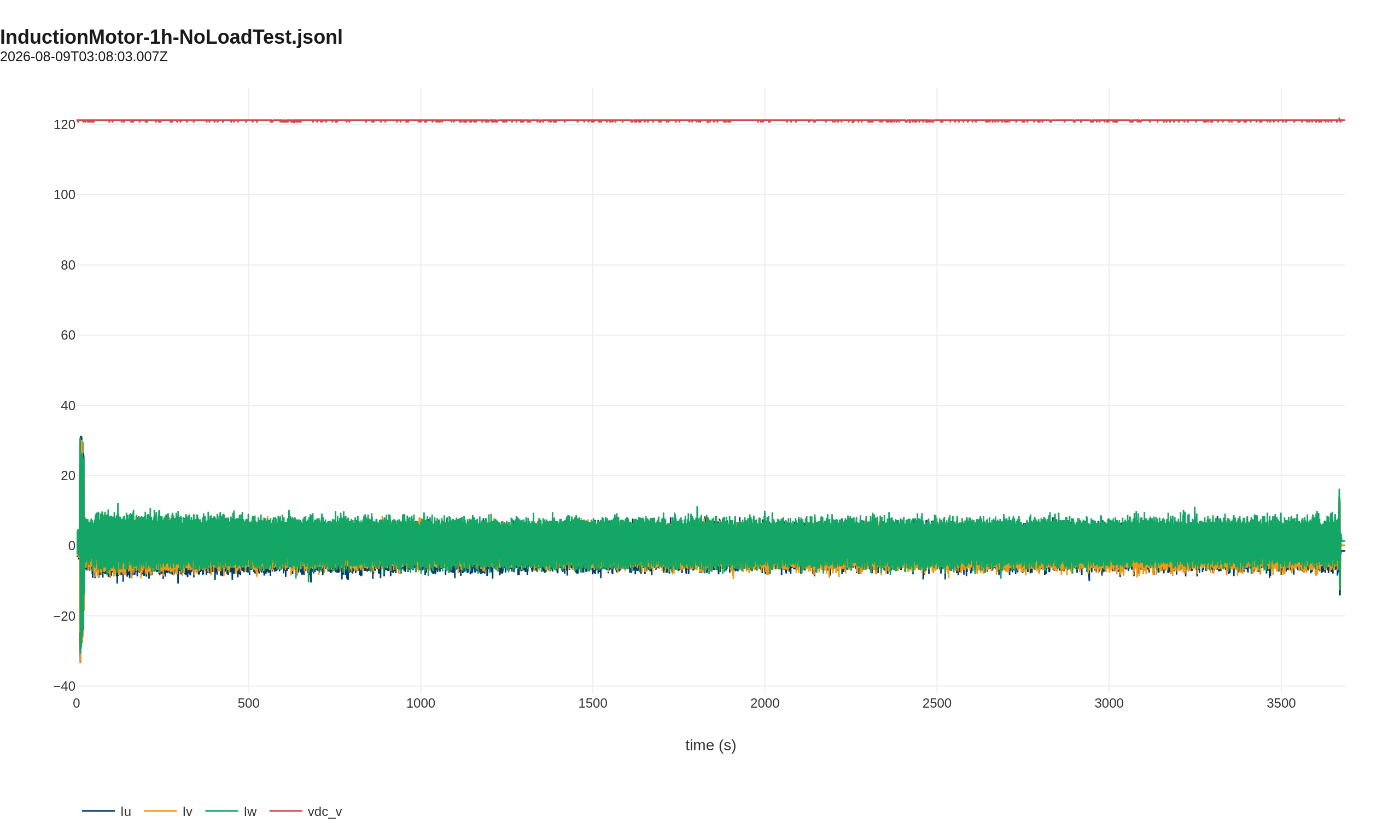
Open telemetry log: View the 1-hour run in the Telemetry Viewer
Conclusion
The C2 inverter and gate-drive subsystem ran continuously for one hour at 120 VDC with no load without fault. The motor temperature rise was modest and consistent with no-load losses. This run establishes a baseline for future loaded thermal tests and confirms the V/Hz drive is functional on the induction machine.
Artifacts
- Decimated telemetry log (JSONL, 1 s) - open in Telemetry Viewer
- Test setup photo (JPG)
- Motor stator photo (JPG)
- Thermal images: 7 min, 21 min, 51 min, 57 min
Notes
- The full-rate telemetry log is ~164 MB; the linked file is decimated to 1 sample per second for the repository.
- Hotspot readings are from the Klein TI250 cross-hair; exact measurement location varied slightly between shots.