6 · v0.2 · draft · 2026-08-09
| Doctype | Test Report |
|---|---|
| Product line | openvvvf |
| Applies to | openvvvf-control-module, chassis-size-2 |
| Version | 0.2 |
| Date | 2026-08-09 |
| Status | draft |
| Description | Validation of the inverter motor-inductance calibration routine on a TECO MAX-IE3 induction motor. |
| Test id | 6 |
| Nav order | 353 |
| Normative refs | OV-TEST-HW-INDUCTION-CAL-INDEX, OV-TEST-HW-INDEX |
Inductance Calibration Validation
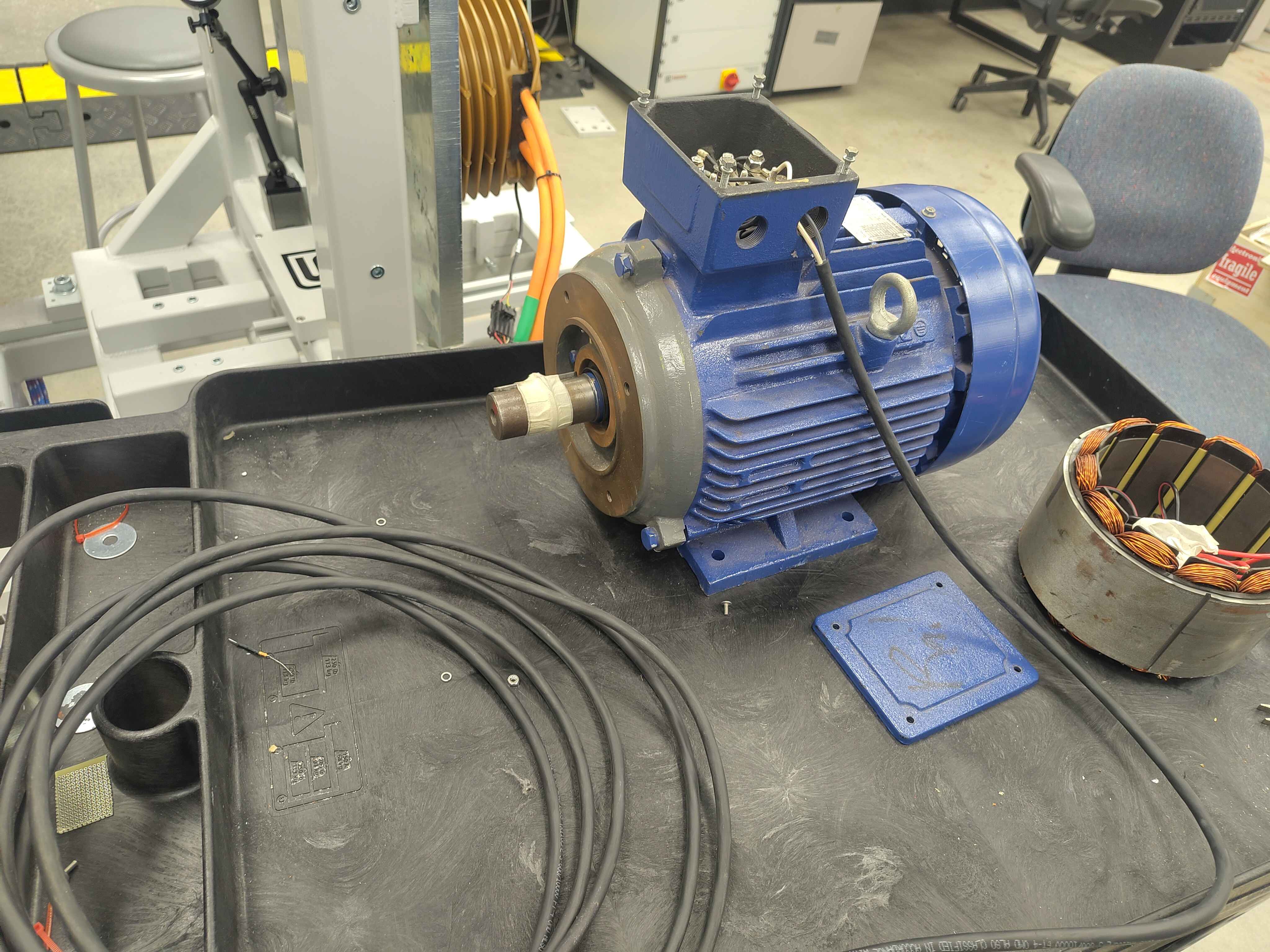
This report validates the inverter's cal Motor.Induction.VHz routine on a TECO MAX-IE3 7.5 kW induction motor. The test is run on the C2 chassis test fixture; the routine itself is shared across all OpenVVVF chassis.
Test setup
The motor is the same TECO Westinghouse MAX-IE3 3-phase induction motor used for the resistance calibration. Phase leads are accessed at the conduit box for direct LCR measurement.
Reference measurement
| Parameter | Value | Instrument settings |
|---|---|---|
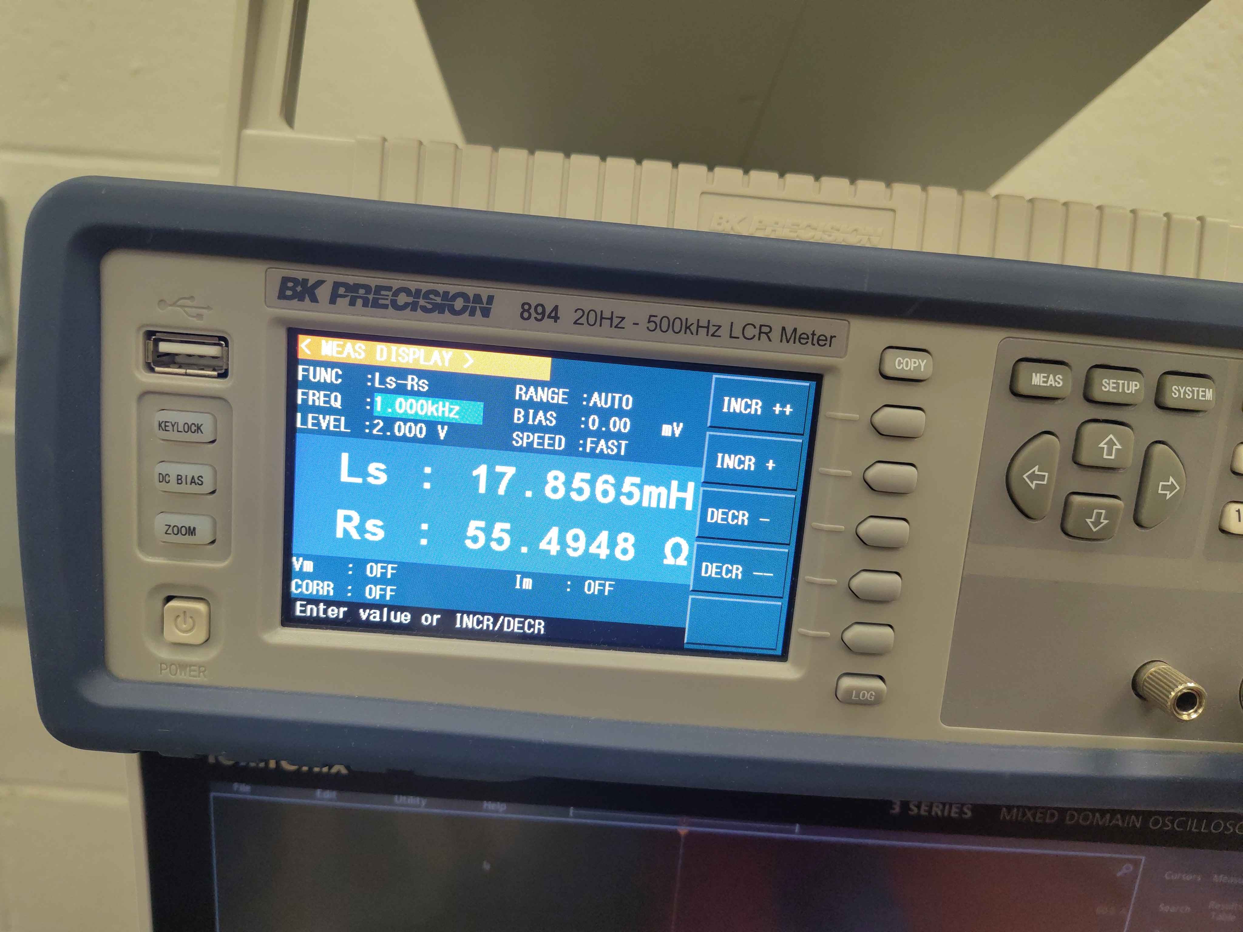
| Ls | 17.8565 mH | FUNC: Ls-Rs, FREQ: 1.000 kHz, LEVEL: 2.000 V, RANGE: AUTO, SPEED: FAST |
| Rs | 55.4948 Ω | FUNC: Ls-Rs, FREQ: 1.000 kHz, LEVEL: 2.000 V, RANGE: AUTO, SPEED: FAST |
Inverter calibration result
Command: cal Motor.Induction.VHz
The routine applies a 10 Hz V/Hz excitation and hunts for a modulation index that produces roughly 5 A of phase current. It then sweeps several modulation points around that operating point and reports the calculated series inductance Ls at each point. The test was repeated at three DC bus voltages to check consistency.
40 V bus run
| Point | Modulation | Current | Phase | Ls |
|---|---|---|---|---|
| 1 | 0.182 | 3.28 A | 136.9° | 20.86 mH |
| 2 | 0.221 | 4.28 A | 139.0° | 18.68 mH |
| 3 | 0.260 | 4.68 A | 142.1° | 18.78 mH |
80 V bus run
| Point | Modulation | Current | Phase | Ls |
|---|---|---|---|---|
| 1 | 0.084 | 2.98 A | 136.0° | 21.71 mH |
| 2 | 0.102 | 3.98 A | 137.7° | 19.19 mH |
| 3 | 0.120 | 4.71 A | 140.1° | 18.14 mH |
Points 4 and 5 were rejected because the current dropped below the slip threshold.
120 V bus run
| Point | Modulation | Current | Phase | Ls |
|---|---|---|---|---|
| 1 | 0.056 | 3.01 A | 135.9° | 21.62 mH |
| 2 | 0.068 | 4.00 A | 137.7° | 19.15 mH |
| 3 | 0.080 | 4.74 A | 140.2° | 18.06 mH |
| 4 | 0.092 | 4.04 A | 145.0° | 21.80 mH |
Point 5 was rejected because the current dropped too low.
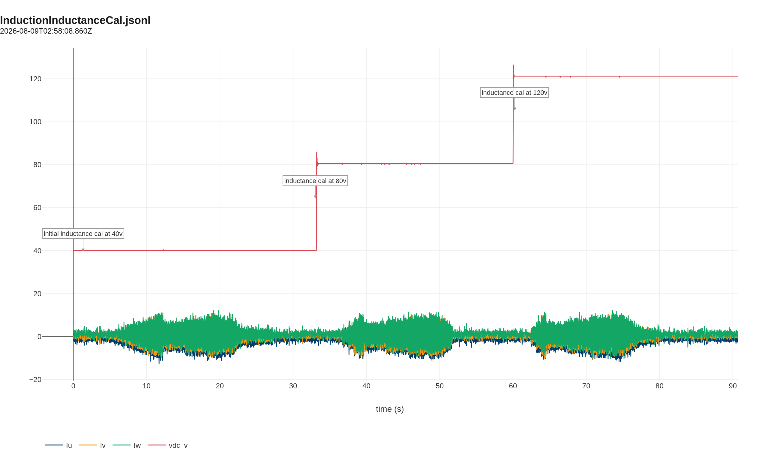
Open telemetry log: View this calibration in the Telemetry Viewer
Comparison and conclusion
The highest-current point in each sweep is the most reliable because the phase voltage across the inductance dominates the IGBT knee and dead-time offsets. Averaging those points:
| Quantity | LCR reference | Inverter estimate | Difference |
|---|---|---|---|
| Ls at ~4.7 A | 17.86 mH | ~18.3 mH | +2.4 % |
The inverter estimate is within a few percent of the LCR reference. The small positive offset is expected: the inverter measurement is taken at a few amperes of excitation current, where slight saturation can raise the apparent inductance compared with the 2 V LCR reading, and the V/Hz estimate includes a small resistive drop correction.
For motor-control purposes, this level of agreement is acceptable. The calibration gives a consistent inductance value across 40 V, 80 V, and 120 V bus levels.
Artifacts
- Telemetry log (JSONL) - open in Telemetry Viewer
- Static inductance plot (PNG)
- Static inductance reference photo (JPG)
Notes
- The Ls-Rs reading is the series inductance and resistance at 1 kHz from the LCR meter.
- The
Rsvalue at 1 kHz is the AC series resistance; it is not the same as the DC resistance recorded in the resistance calibration report. - This motor is an induction machine, not a PMSM, so it is tracked separately from the PMSM calibration report.